A WeMos based DirectDrive SP-101 Clock
Following on from my Smart-Socket based SP-101 clock invention I decided to make a version driving the same displays using HV5622 shift registers.
This would allow for a more compact design consisting of two boards, one to hold the displays and another for the power supplies and controller.
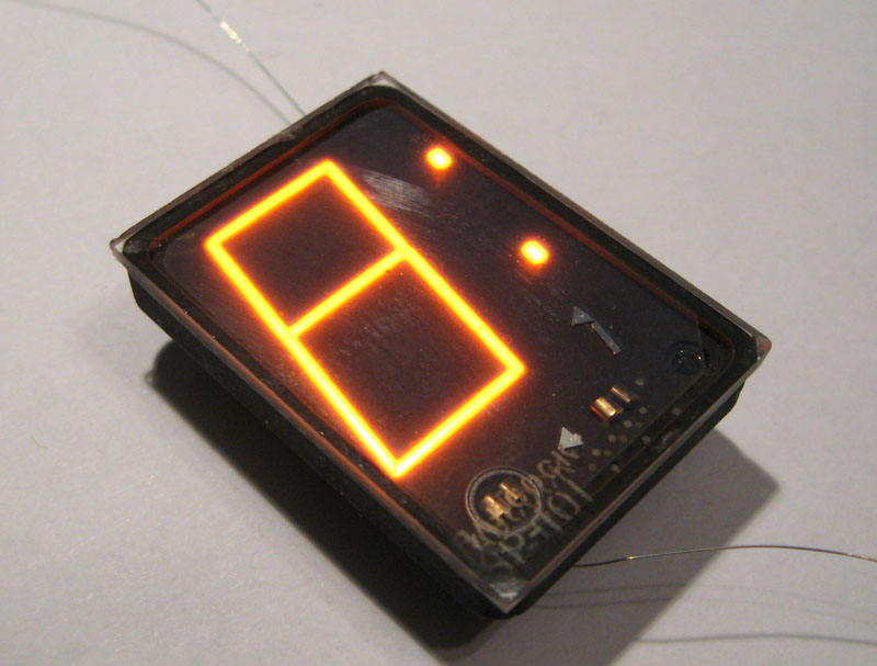
The displays are not that common and even less common are the sockets used to hold them. For this project I used recepticles from turned pin IC sockets which had been broken out of their plastic surrounds and soldered directly to the board. This allowed the creation of a board to hold six SP-101 with no additional hardware and the displays held in sockets which meant that they could be eiasily removed if required.
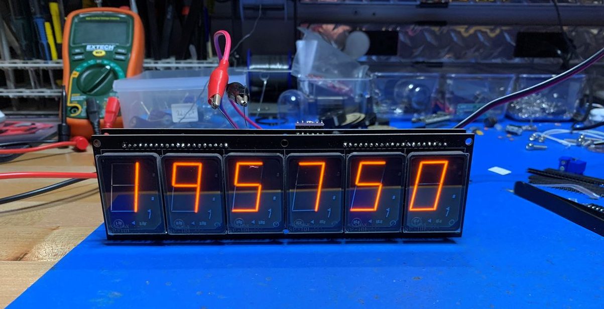
SP-101 6 digit WeMos based Clock
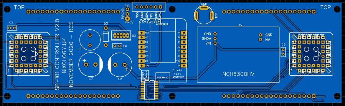
EasyEDA presentation of how it should look
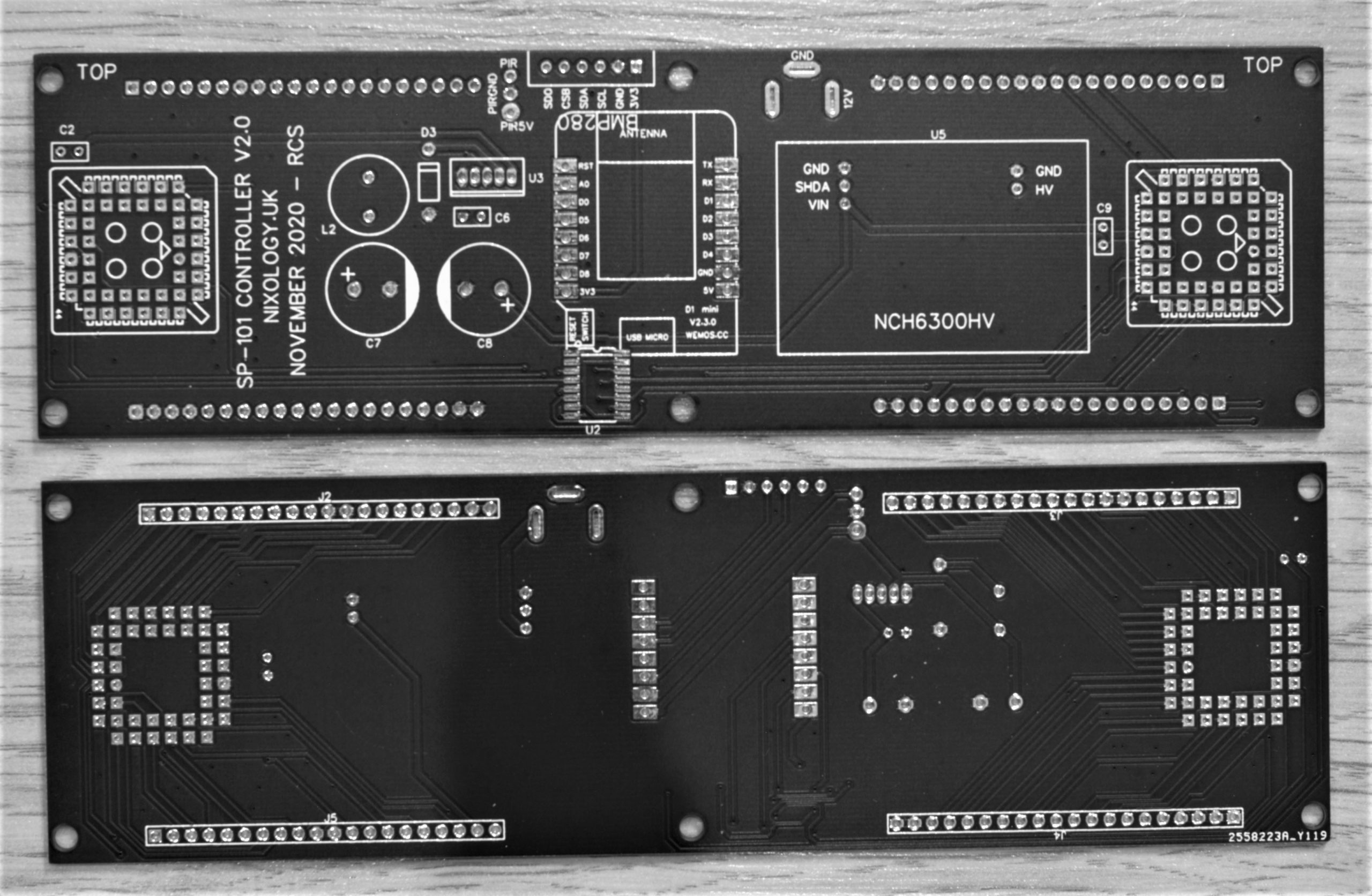
How the boards actually turned out
The controller board uses a WeMos micro controller to drive the displays via HV5622 shift registers. The HV5622 like to be driven at 12V logic levels so a CD40109 level shifter is employed to convert the 3V3 signals to 12V.
Also on board is an LM2696T-5 based 5V power supply and an NCH6300HV 170V power supply.
Originally I used an MC34063 based circuit for the 170V though at the time I was experiencing issues with that so for this project I elected to use the new NCH6300HV from Omnixie.
I have subsequently resolved the issues that I had with the MC34063 based design so if I were doing this again, I could revert to that.
The board also has two HV5622 shift registers which link to the display elements via series resistors for cathode current control. PLC44 based versions were chosen because space was not an issue – and I had a few on hand!
The two boards fix together via 4 x 20 pin 0.1″ headers and sockets. There are mounting holes that can also be used to fix the boards together as well as mount it in your chosen housing.
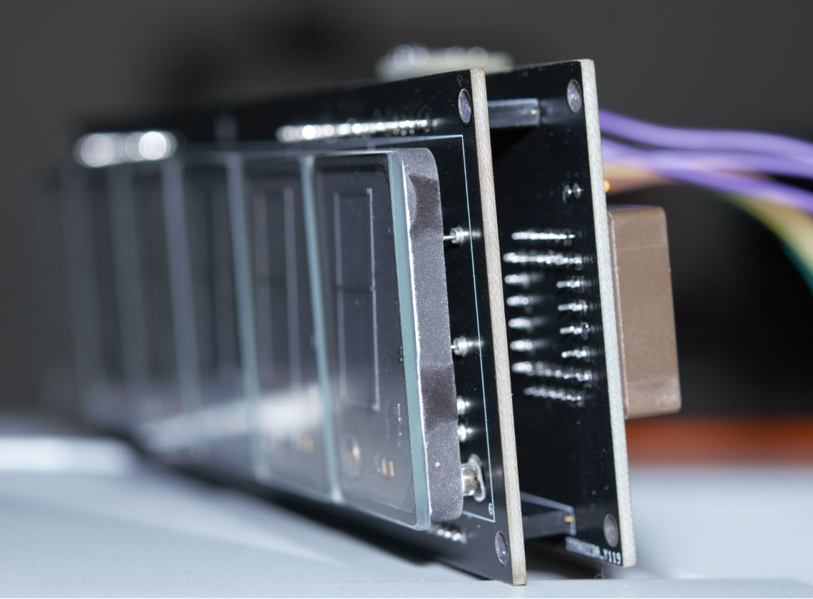
The display board has the SP-101’s mounted using the turned pin IC socket pins that have been broken out of their plastic surround which allows the SP-101’s to be inserted/removed/replaced with relative ease.
The back of the board is where all the series resistors live, one for each cathode, the values vary depending on whether it’s connected to a short segment, long segment, colon, comma or decimal point.
Four twenty way pin headers provide the interconnections to the controller board which are mostly segment connections to the shift registers as well as the HV supply and ground (not needed for circuit operation but all the boards have a generous ground plane on each side).
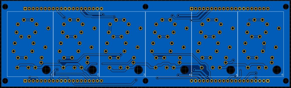
EasyEDA presentation of how it should look
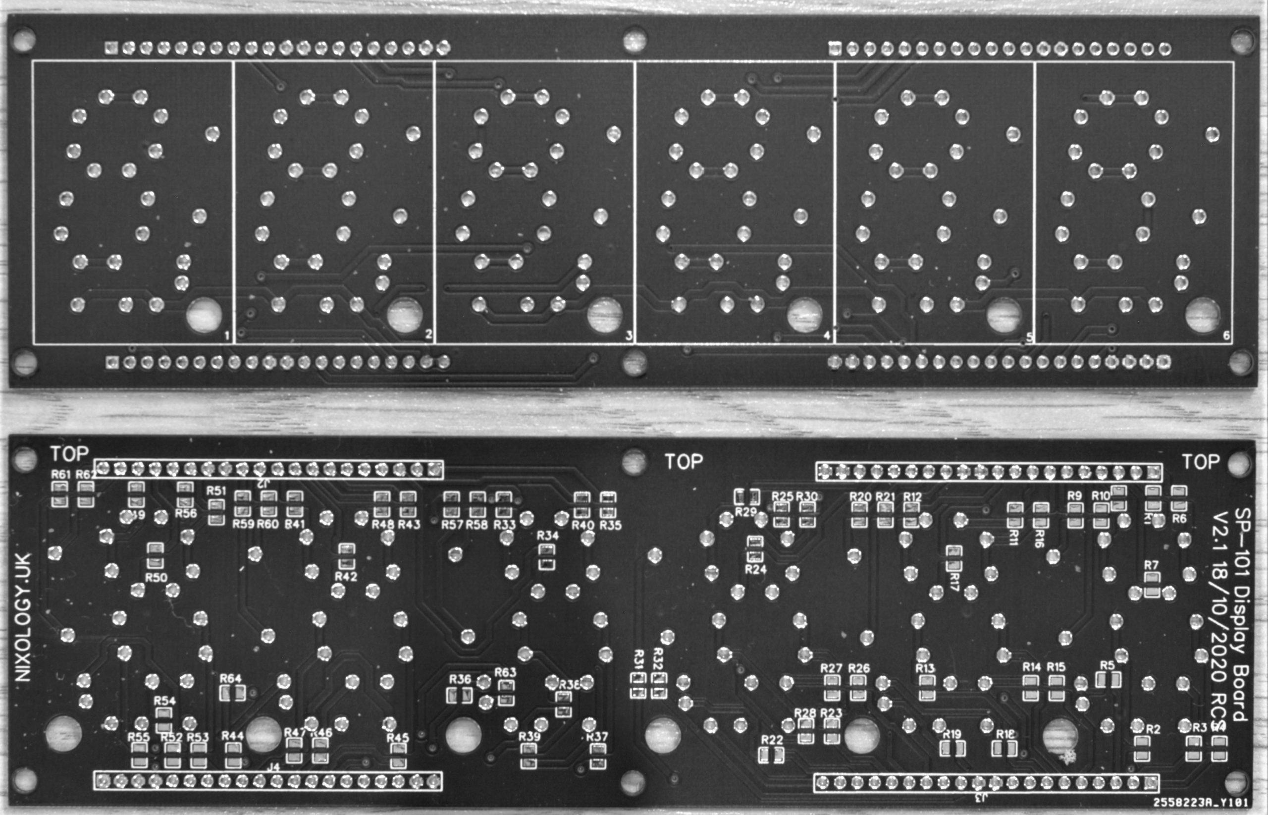
How the boards actually turned out
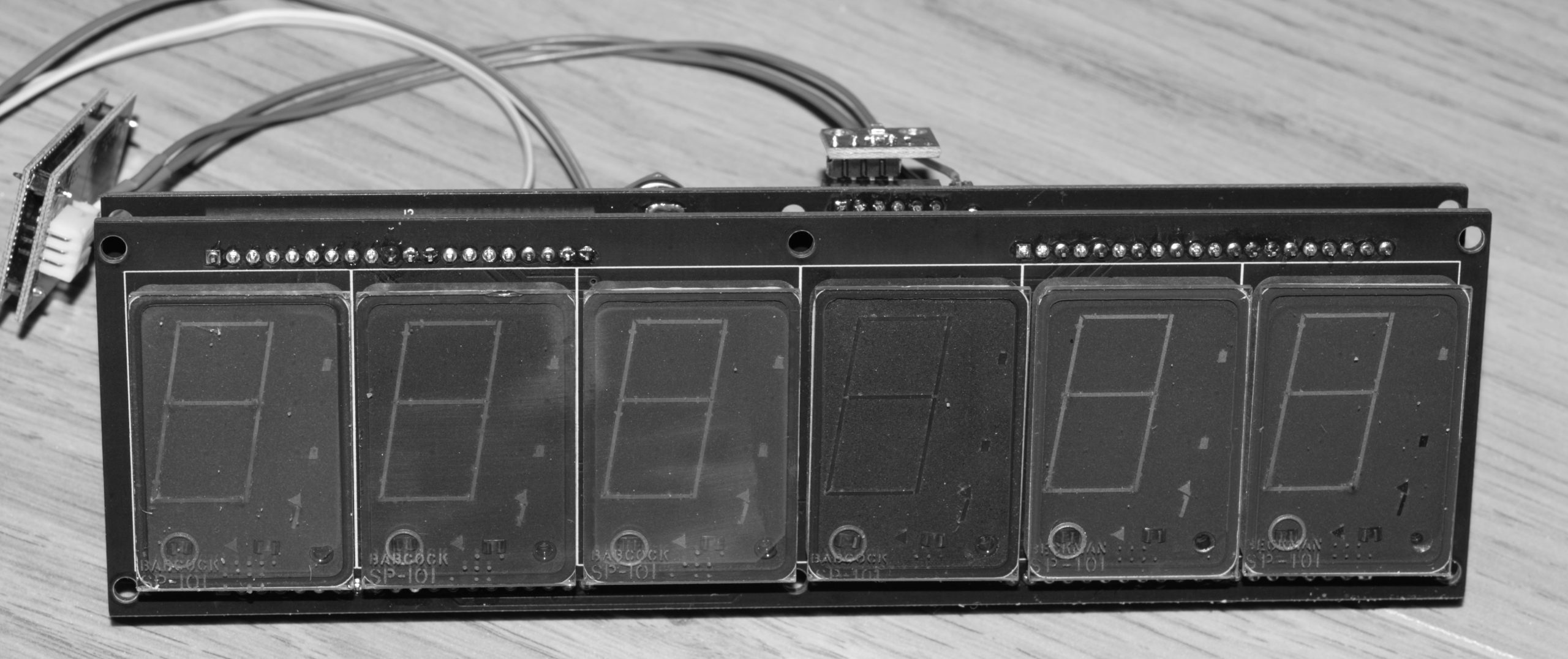
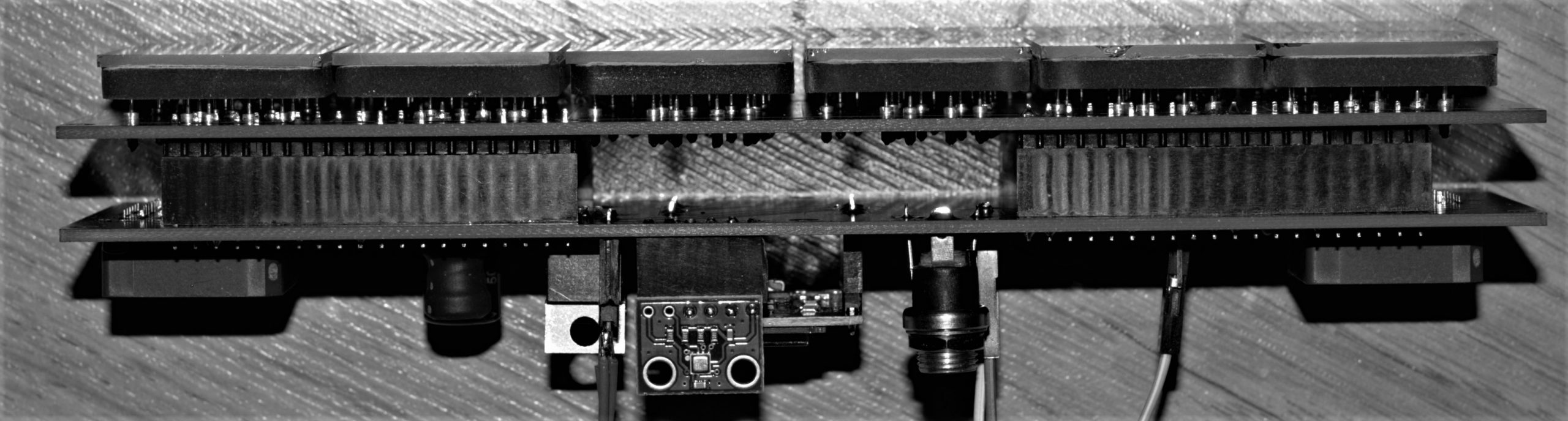
Font view of the completed sandwhich
Top view showing interboard connections and BME280 sensor
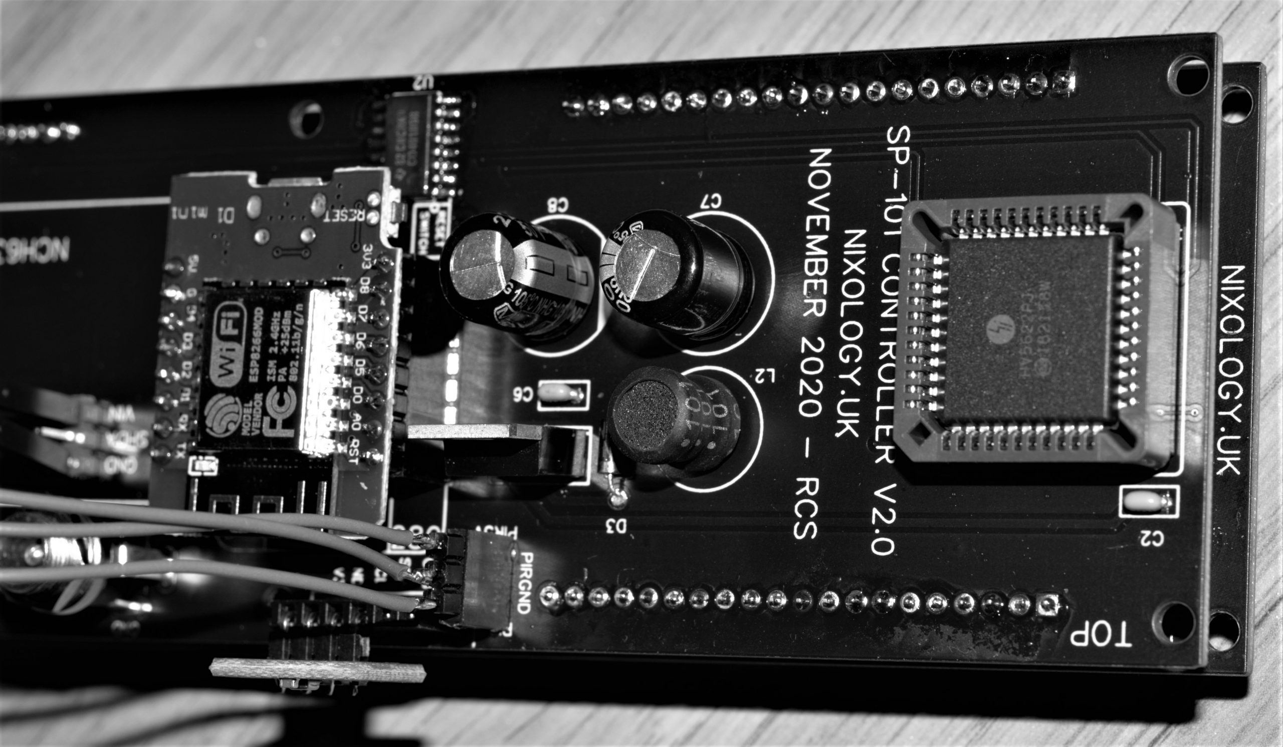
Random picture of one end of the controller showing 5V PSU
General Operation
The WeMos takes care of connecting to a WiFi signal and syncing time with an NTP source. It also reads a BME280 sensor for the temperature and pressure. It also reads a motion detector (if connected) so that the displays are only illuminated when someone is there to admire them.
The two shift registers need to be fed two 32 bit values in order to display the required information. The data is sent using SPI data transfers for the best possible speed.
There are two arrays which map the designated display segments (A to G) and objects such as Decimal point and Colon etc to the physical pins on the shift registers.
Separate arrays hold the definitions of the numbers and characters that might be displayed.
When it comes to displaying the required information, a single routing is called which specifies the 6 digits to be displayed as well as the state of the colon. In the current version, neither the decimal points or commas are used. Colon parts are used for the degree symbol when displaying the temperature.
Boards and bits
If you have access to a set of SP-101 displays and would like to build this project then I would be pleased to help.
I can provide sets of boards and a B.O.M. or a complete kit of parts (excluding displays and power adapter).
The software source is provided ‘as is’ and will run the clock, alternatively it could be used as a basis for your own code – or even ignored completely!