Why use a smart socket?
Driving a nixie tube is one thing, grounding out one of 10 cathodes to diplay a single digit when required is the way that most nixie tube clocks work.
There are however, a number of devices which use multiple segments to create the desired character. Devices such as B-7971 and ZM1350 have up to 15 individual segements, any of which may be used to display numbers, letters or symbols.
In order to simplify this process for the clock building enthusiast, Smart Sockets were created.
These mostly consist of a single board that holds the display device along with a PIC micro controller and a transistor to switch each segment of the display on when needed. The code in the PIC expects commands to be sent via a serial interface and smart sockets can be connected together to make clocks or display devices with up to 255 individual digits!
There is good community support for the smart sockets and the design and code are published under an open source agreement.
So far I have used smart socket technology to build clocks using B-7971 tubes from Burroughs, ZM1350 Panaplex displays from Telefunken and SP-101 panaplex displays from Sperry/Babcock and my own LED based display which is designed to emulate the increasingly more rare B-7971.
The smart sockets take care of all work required to form characters and provide transition effects. I ‘developed’ ‘Frankontroller’ to drive them.
–
Frankontroller
B-7971 Smart Socket
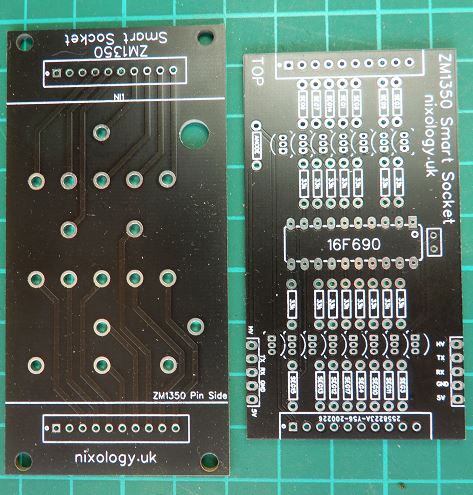
ZM1350 Smart Socket
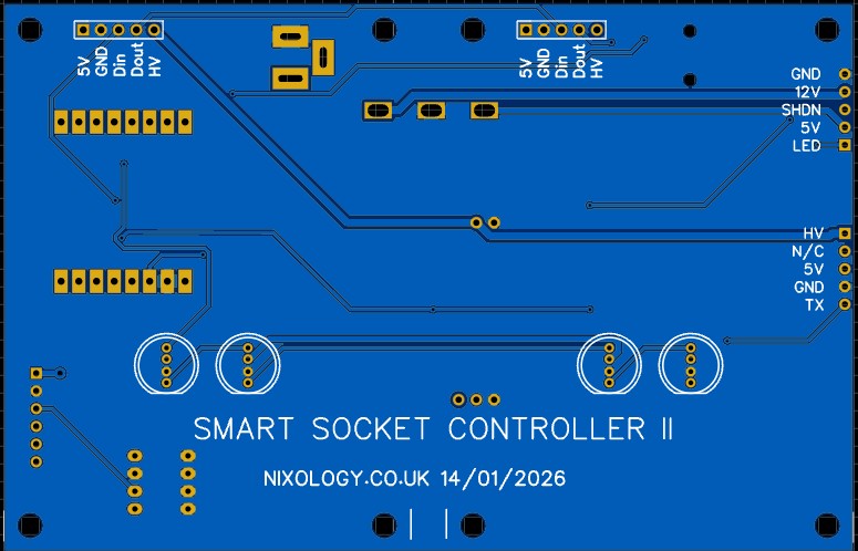
Controller board for two Smart Sockets
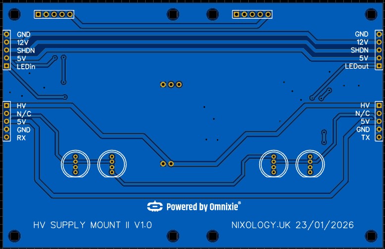
Link board for two more Smart Sockets
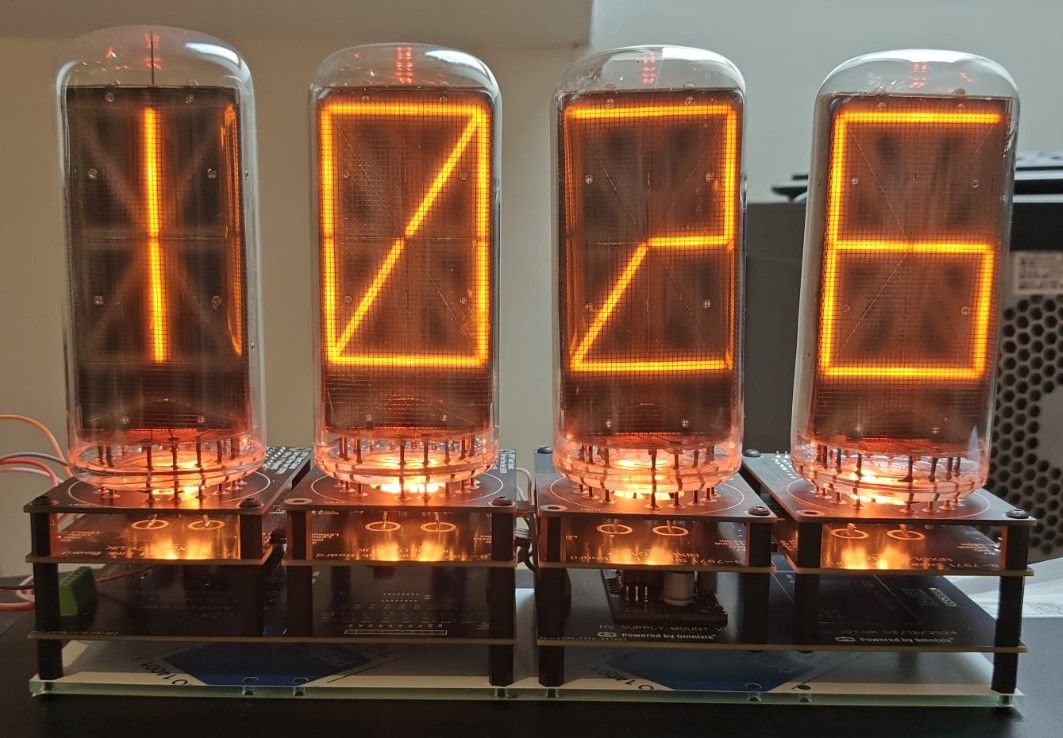
4LW Based on the three board stack
All New Modular Smart Socket based device
For some time I have had a bunch of Smart Sockets made up with the idea of making some form of modular base that provided everything necessary to create a working clock but without the need for lots of wiring between the smart sockets and power supplies etc so I came up with a modular approach.
I wanted to include the micro, 5V and HV power supplies as well as to provide under tube lighting.
Initially I came up with a board that sat under the smart socket, (with the same dimensions) which had addressable LED lighting as well as pads on each side to make the interlinking of individual smart sockets a lot easier. Under that was a controller board that had the 5V power supply and micro for control. The controller board had space for two smart-socket+underlighting boards to plug in to it. A second board of the same dimensions had space for another two smart socket+underlighting boards as well as the HV power supply module. This made it very easy to create a Four Letter Word (FLW) kind of device.
The controller also supported a temperature/pressure sensor as well as a 256K eeprom for word storage.
Some time after I had this running for a while, I integrated the features of the underlighting board onto the controller board which reduced the stack of three boards down to two.