ZM1350 Smart Socket (my own layout) development
The ZM1350 Panaplex display can be used in Smart Sockets like those available from members of the smart-sockets group for the ten digit Panaplex display clock that I still have not got in to a box yet (Covid delay).
The original smart socket concept was first published around 2006 when I expect that displays such as B-7971 and ZM1350 were available in abundance and at a price that didn’t hurt anywhere near as much as it does today some fourteen years later.
I have arrived very late at this particular party and fully appreciate that everything I am doing has been done before by many people. This is a record of my journey of discovery in the smart socket arena!
I decided to have a go at making my own Smart Socket for these displays. The design objective being to make the boards with as small a footprint as possible.
Usually this means mounting all resistors on their ends to reduce space. I am not a great fan of this so I elected to make two boards. One to mount the display and one to mount the PIC and all associated resistors and transistors.
The two boards would sandwich together and connect using two rows of 0.1” turned pin/sockets.
The circuit for doing this is well established. It was simply a matter of laying out all the components as desired and within the confines of my capabilities.
For me this meant that all resistors should be flat against the board and the MPSA42 transistor footprint should allow the transistor to sit flush against the board – so many designs seem to need their legs splaying apart which means that they have to sit away from the surface of the board. There may actually be a good reason for this – heat dissipation perhaps?
In doing this and in order to make the board layout as simple as possible, it meant that the assignment of display segments to PIC ports needed to be changed. This is handled in the software for the PIC which I am slowly getting to grips with.
Another design consideration was to present the TX and RX connections on both sides of the board so that, when daisy chaining, the ‘order’ of the boards could be in either direction. All that needs to be done is the TX of one connected to the RX of the next one according to whether the chain was running from right to left or left to right.
A map of which port on the pic was connected to which segment on the display was created. This is needed not only for the software changes but, as each segment of the display requires a different value of series resistor, it is necessary to know which one is which so that the correct value resistor is used for each segment. The segment lengths vary, hence the need for different current limits and therefore different series resistor values.
The boards were designed, ordered and delivered. The time came to put one together for testing.
Everything was hooked up; I used a PIC from a B-7971 smart socket and powered the thing up.
The display sprang into life and, unsurprisingly started to display what looked more like ‘Klingon’ or ‘Predator’ style characters. I changed the data that was being sent so that each segment was illuminated individually in turn and the sequence was displayed with the expected randomness. Time to look at the code in the PIC.
The code is well documented by the author Chris Barron and is provided under a GPL agreement.
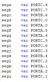
As far as I could tell, there are two sections that deal with the assignment of PIC ports to Display Segments. All that needs to be done is, for each section, change the definition of which PIC port is used for each display segment. Then compile the code, load to a PIC and plug the PIC into the smart socket, job done!
The code refers to segments named with letters a-n and u for the underscore. It seems that the ZM1350 data sheets like to use numbers 1-15 and in a reverse order – I will stick to the a-u convention as used on B-7971 smart sockets
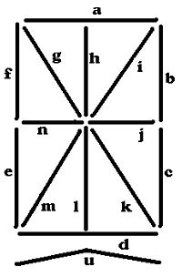
Segment letter assignments
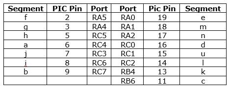
Assignment of PIC Ports to Segments
PIC Code Mods
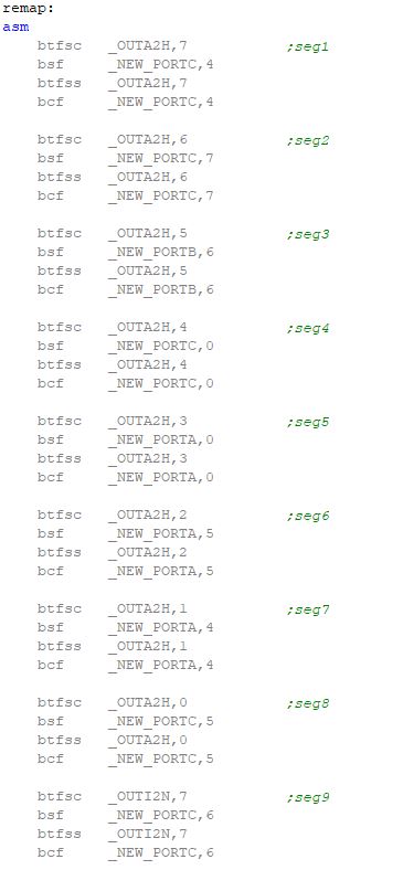
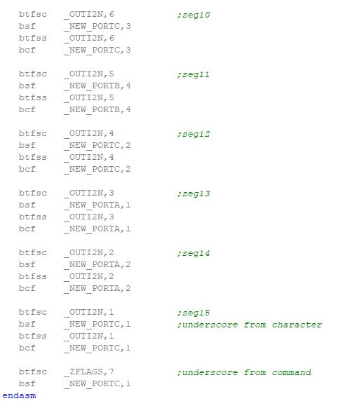
More PIC Code Mods
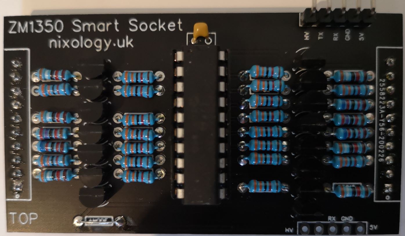
Controller Component board
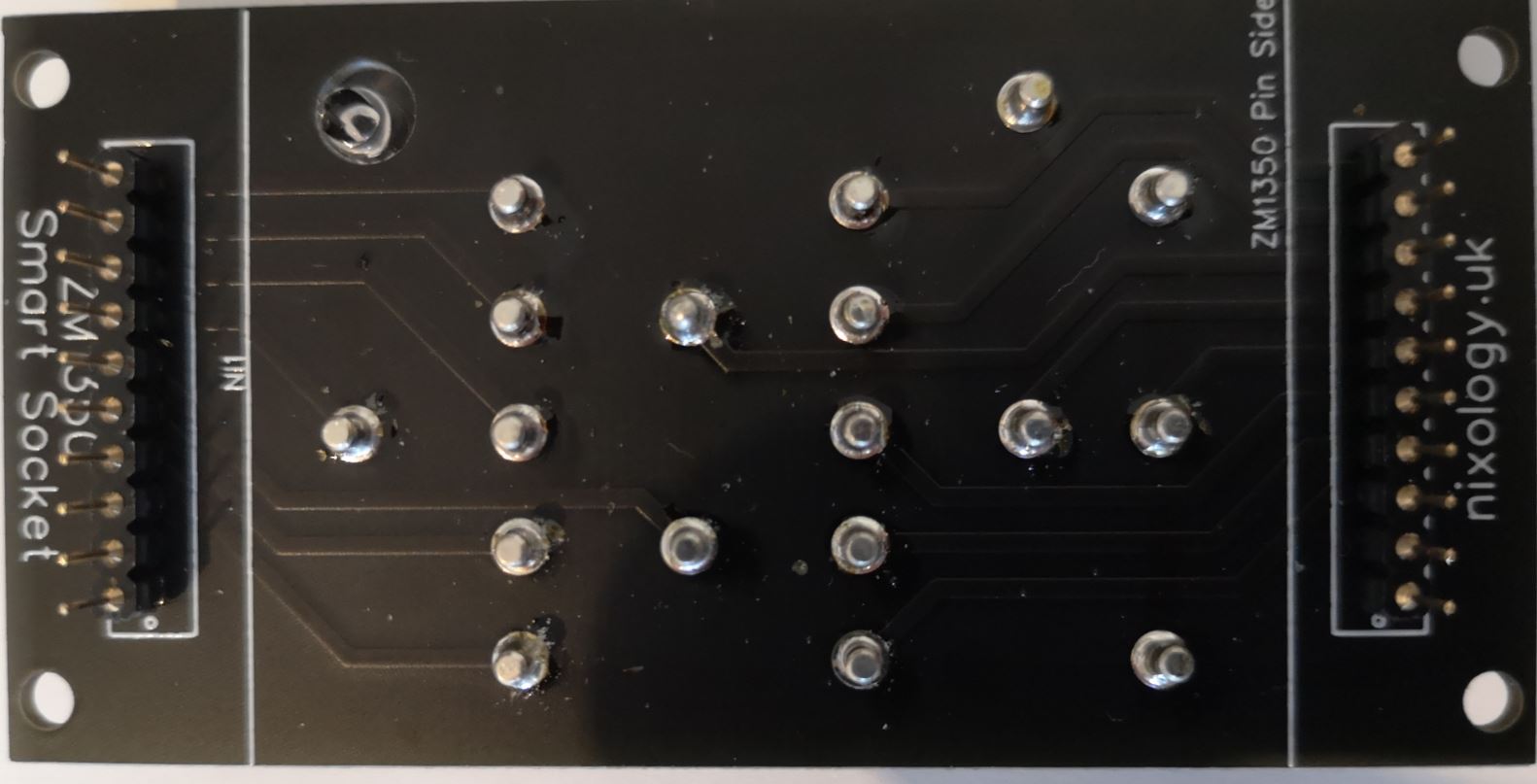
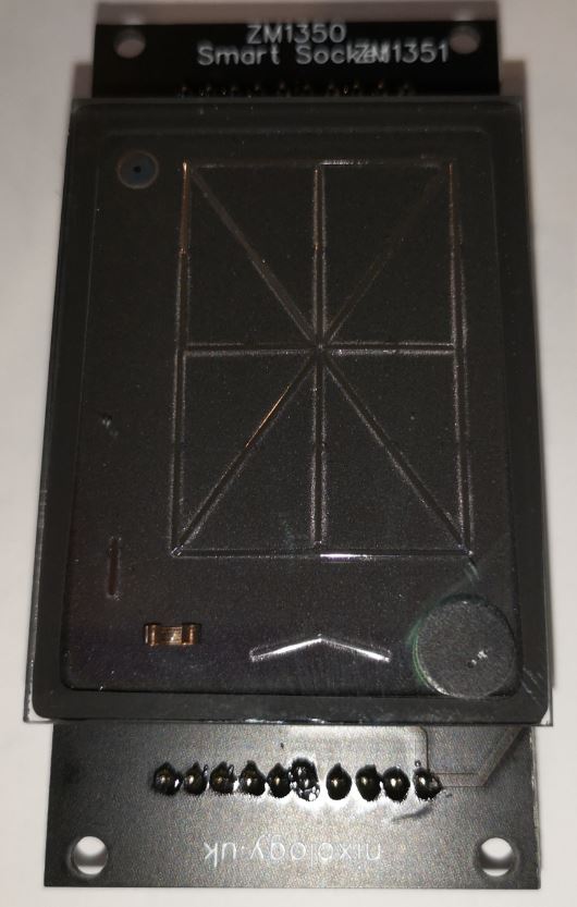
Display mount – rear view
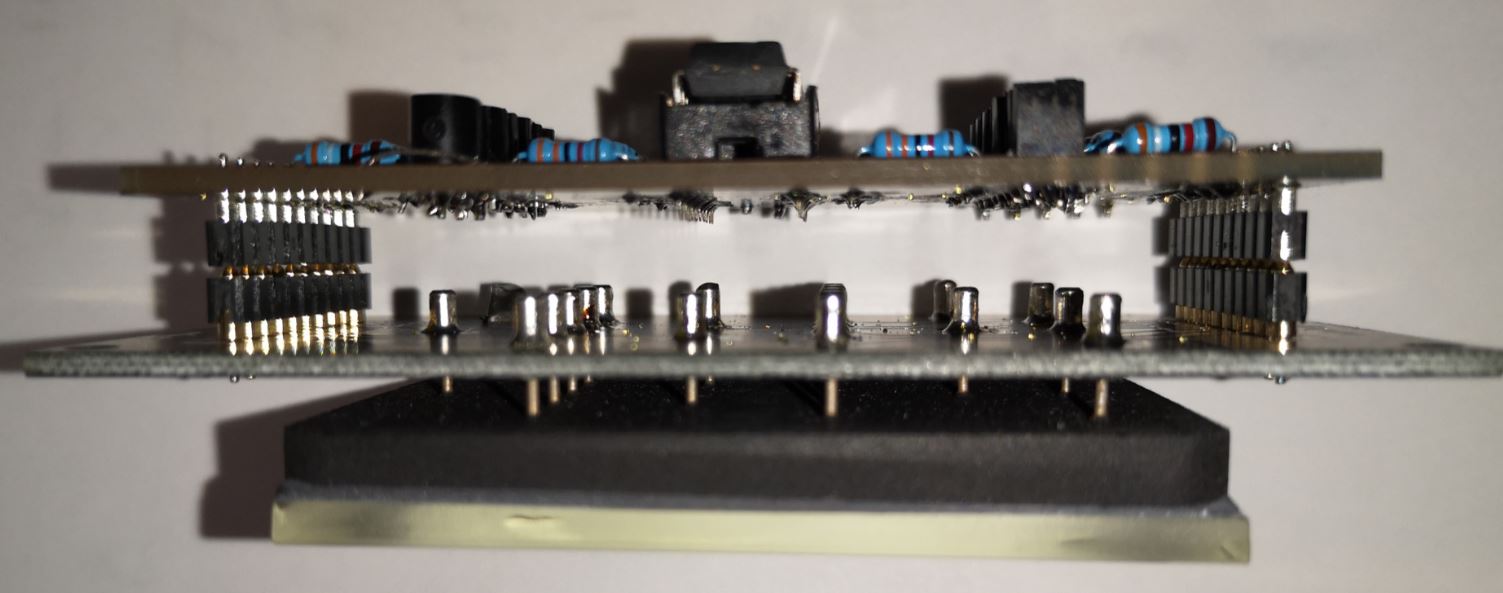
The completed sandwhich
View from the top
How did it go?
At this point I feel that I should mention my first attempt at this was based on numeric segment assignments from the ZM1350 datasheet which numbers the segments in a mirror fashion when compared with the B-7971 data sheets and accordingly, when I powered the thing up – all the characters were ‘reversed’ – Doh!
So, the board layout works, the code in the PIC works and the display works. Everything points to happiness.
The next step will be to make up five more boards to drive a total of 6 displays.
I also need to lay out a small thin board which will hold two neons and associated drive electronics (resistors and transistors) which will sit between displays to act as colons, decimal points and degree symbols for all the different types of data that I want to display.
I am contemplating putting a pair of neons between each display for total flexibility (overkill I know) but as the boards come as minimum order of five and then with panelisation I’ll probably end up with twenty five for the same cost, why wouldn’t I!
The whole thing will most probably be driven by Frankontroller III which I am using on a number of other smart-socket based projects.