Beckman Panaplex Display Clock
A while ago I was fortunate to acquire a set of Beckman SP-101 1” Panaplex displays along with their associated sockets. These displays were actually available from Beckman, Sperry and Babcock. They work on the same principle as Nixie Tubes but are a multi segment flat package design based on a 7 segment LED display along with some dots for colons, a full stop and a semi colon.
To illuminate each segment, a voltage in the region of 170V is required. Each segment needs a series resistor to limit the current (typically 700uA for the larger segments) with a maintaining voltage of around 135V. Hence the value of the resistor R=V/I, R=(170-135)/300uA = 35/700uA = 50k, I decided to limit the current a little further an used either 62k or 68k resistors for the main segments. The colon segments, decimal points and comma need significantly less (100uA to 200uA) so 350K or 175K (typically) were used. In total, each display has 11 elements that need to be switched on or off in order to make up the character to be displayed. Being only 7 segments the available characters are limited mostly to the digits 0-9 as well as some rudimentary letters such as A,b, C, d, E and F although with some imagination it is possible to render the entire alphabet! I needed a way to control all the elements of the display so that I could display numbers, some letters and the various additional punctuation elements. This could easily be achieved using HV shift registers as has been done in many Nixie clock designs. I had become familiar with the ‘Smart Socket’ concept after building clocks with Burroughs B-7971 and Telefunken ZM1350 displays. These multi segment displays are based on up to 15 elements and allow their control by sending ascii strings to each display. Because of the work I had already done with these I decided that was the route for me.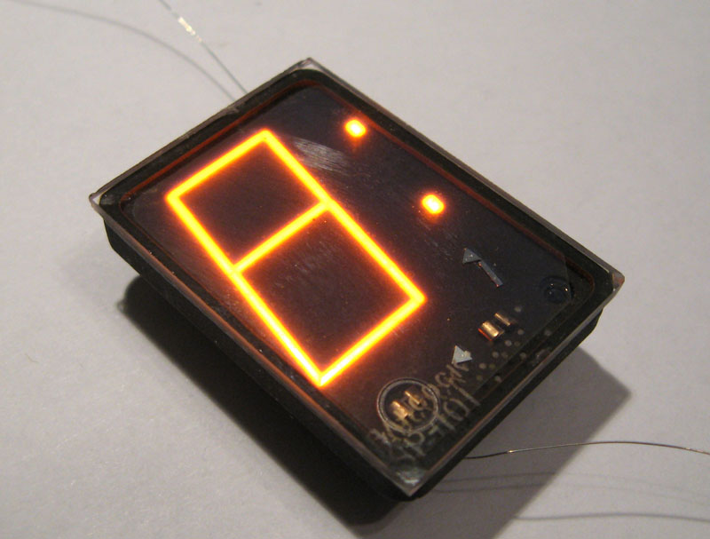
Babcock SP-101 Panaplex Display

B-7971 Smart Socket
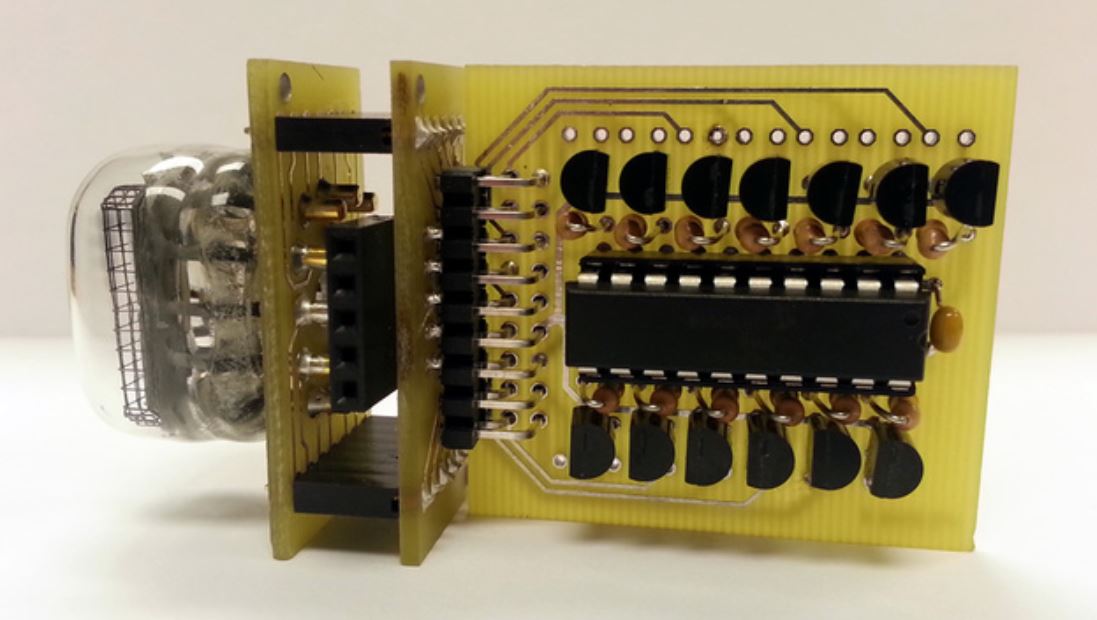
B-5971 Smart Socket with tube attached (not my picture)
B-5971 Smart Socket
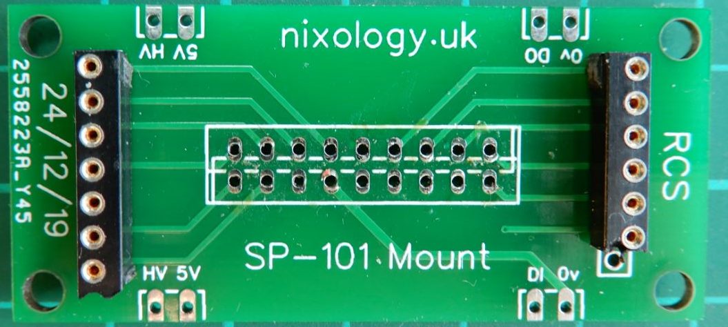
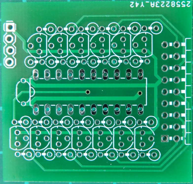
SP-101 Mounting Board
Smart Sockets
A while ago, Chris Barron came up with the concept of Smart Sockets as a method of easily controlling multi segment displays such as the Burroughs B-7971 display tube which is made up of 15 different elements.
The Smart Socket uses a PIC controller and associated electronics to control the segments from simple command strings. In this way, the tube can be made to display all characters from A-Z and 0-9 as well as various symbols. The Smart Socket also provides various fading options as well as user defined characters. See the attached Smart Socket PDF for more information. There is a Smart Socket user group at: https://groups.io/g/smartsockets The Smart Socket for the Burroughs B-7971 is designed to mount the tube right on the main board. I wanted to connect to a completely different type of display. A Smart Socket for the Telefunken ZM1350 display had already been designed and then another for the Burroughs B-5971, another multi segment display. The Smart Socket boards and code are made available under a generous GPL agreement which I hereby acknowledge. The B-5971 board interested me because the main board that contained the PIC and all associated electronics then connected to another board which held the display. I decided to use this board layout and then design my own board to hold the SP-101 displays. Ultimately each completed ‘module’ consisted of the controller board, a board to mount the display and an intermediate board to marry the other two together. Once the boards had been assembled, I also needed to modify the code in the PIC as the existing code was set up to drive 15 elements to make characters. I was using on 11 elements, 7 of which were for forming the characters, the others were for the various punctuation options. Getting my head around the code was a bit of a stretch as it required deployment and learning of a whole new development environment as well as understanding and then modifying someone else’s code. I got there in the end. I ended up with characters for 0-9 as well as A-Z all based on the 7 segment displays. In order to activate the colon sections etc. I repeated the character definitions using the User Defined Character (UDC) feature of the PIC Code. Thus I had a definition for each character on its own, then again with upper colon dot, lower colon dot, full colon, full stop and comma etc. All I needed to do was to manage this in the data that I was sending to the Smart Sockets in order to activate whatever parts of the displays were required.Frankontroller Development
I had done some work with things like the WeMos D1 and Node MCU boards which both feature the ESP8266 WiFi module.
I have used these to make simple NTP sync devices for Nixie Clocks where the board will connect to the internet, sync time with an NTP source and then periodically send a sync string out on a serial line to a clock which is designed to accept GPS strings such as the excellent Spectrum clock range from PV Electronics. I decided that I would expand the code inside this in order to send the required strings to the Smart Sockets. Simples I thought. At the same time, I learnt the concept of the ‘State Machine’ method of programming which basically means that the main code loop can thrash around at full speed and at required intervals (every second for example) it could make the required changes to the data being displayed. All programmed in a non-blocking way. However, I hit many problems whereby whatever I did I ended up with Watchdog Timer Resets on the ESP-8266 device and I am not sufficiently skilled to work around these issues. I elected to go a different way. I used a simple Arduino Nano device to run the State Machine Code. This allowed me to send strings to the smart sockets every second to display the time. It also then allowed the display of other data (date etc) at pre-defined intervals. All the time the main loop executed hundreds or thousands of times every second whilst the display was updated only when needed. This method also allowed the controlling of things like colons made using Neons. The State Machine code read characters coming in on a serial line so it could easily consume and then process the GPS Sync strings in order to set and maintain the correct time. This concept was later expanded on in order to include additional information in the GPS style string such as temperature and pressure (which was read by the ESP-8266 from a BMP280 sensor), a random word from a pre-defined library and latterly, wind speed and direction which I pinched from a local web site. All the formatting of the string is handled by the ESP-8266, the state machine code accepts it and uses it when required to control the display. The state machine code also supports triggering by a PIR / microwave device so that the HV supply can be switched off in order to preserve the precious display devices. Thus the Frankontroller concept was born, a clock controller which consisted of an ESP-8266 device, Arduino Nano, a 12V to 5V buck converter as well as a 170V power supply module. During development I have moved from Node-MCU to WeMos D1 – which is essentially the same thing on a smaller board. I have also moved from Arduino Nano to a Teensy 3.2, this was because I was running out of headroom in the Nano. Code started to fail for no apparent reason, then I noticed that I had consumed most of the memory of the Nano, time to change up a gear or two. I fully accept that the whole thing could be accomplished using a single micro such as an ESP-32 but I lack the skills to achieve that so Frankontroller remains my method of choice. I have recently replaced the $2 12V Buck converter with discrete components to make a 5V supply from 12V. Perhaps I will do the same for the 170V one day. A recent addition was to add connection for an APA106 style LED so that case lighting effects could be added if desired.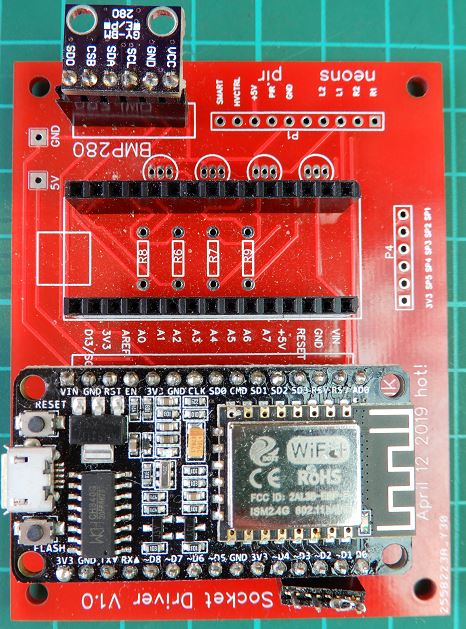
Frankontroller V1.0 with NodeMCU and Arduino Nano
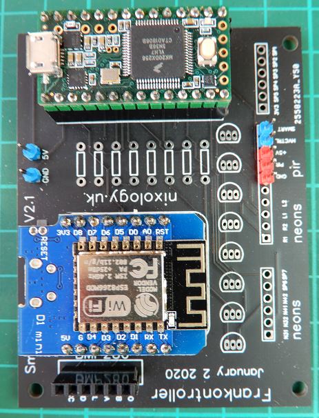
Frankontroller V2.1 with WeMos and Teensy
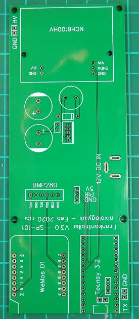
Frankontroller V3.0 with WeMos, Teensy and HV Modules
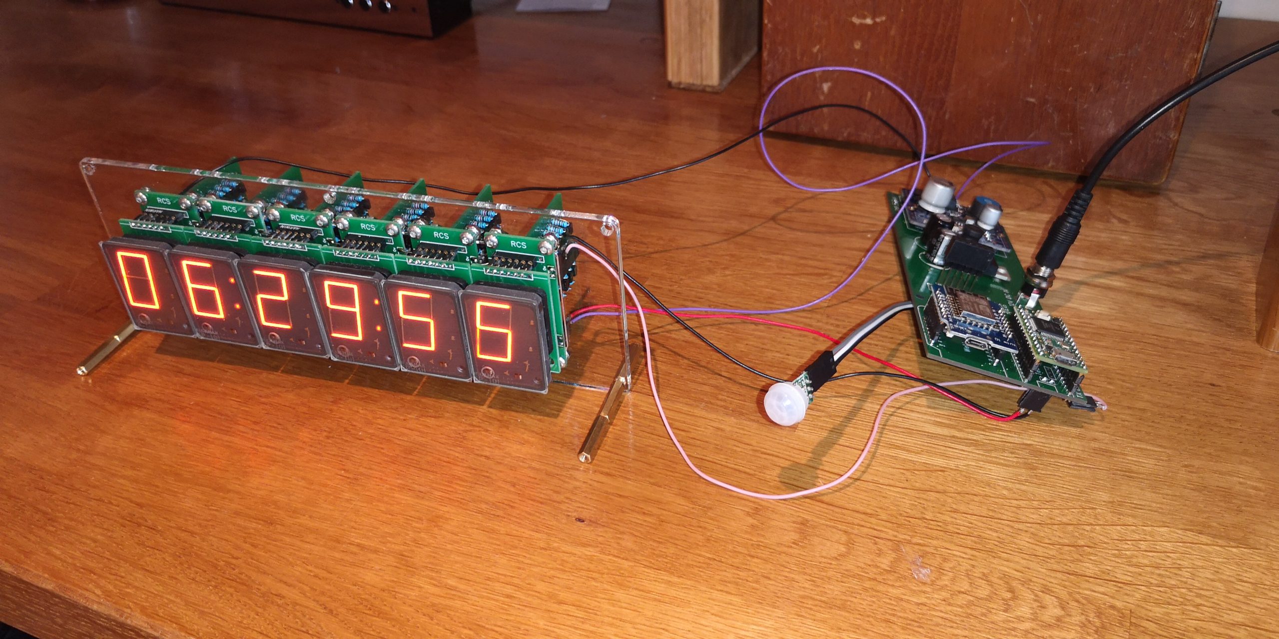
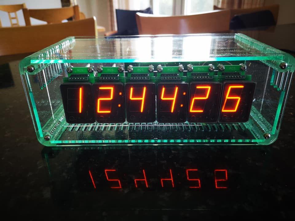
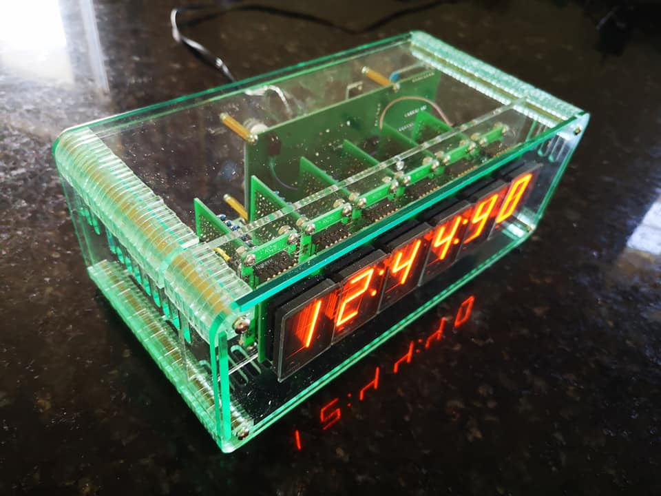
6 digit diplay with Frankontroller V3.0
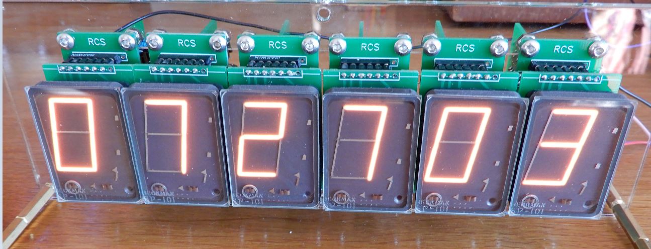
6 digit diplay module with 6 Smart Sockets
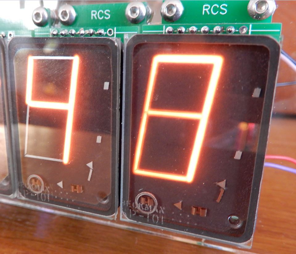
Closeup of Beckman SP-101’s
Pulling it all together
So, the Frankontroller reads time from the internet and combines it with other data in order to maintain a data stream that will feed the smart sockets and display the time and the other information.
There are six Smart Socket boards in a chain which display the supplied data thus providing a clock display which also shows day, month, year, temperature, pressure, wind strength and direction and a random word. All on 7 segment display devices. A PIR or microwave device ensures that the displays are only active when triggered by movement. That’s about it! Beckman SP-101 Datasheet–
Smart Socket Information–
Smart Socket Group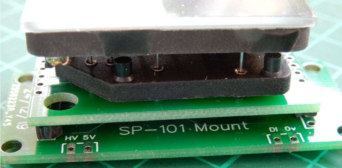
SP-101 display sitting on top the its socket which then connects to a PCB which plugs into a second PCB which then has a 90 degree connection to the B-5971 Smart Socket with customised firmware.