Two Tube Clock Development
Having now built a few of the Gemeni Two Tube Clocks I decided to refresh the design and incorporating various developments that I had learnt in other projects.
The original design had one limitation that bugged me a little which was that it was not best suited to driving IN-18 tubes because of the ‘blue spot’ problem which is fundamentally down to issues caused by using the 74141 / K155ID1 driver. This isssue is well discussed and a quick internet search will tell you more.
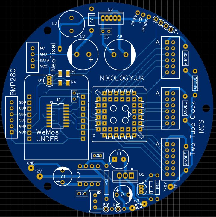
It seemed that a different driver was needed and after some research and testing I decided to use the HV5622 32 bit HV driver which is quite popular and used in several commercially available clock kits. This single chip would replace the two nixie drivers as well as the 74595 shift register.
Another feature of the HV5622 is the blanking input which can be used to control the outputs via PWM – thus the PWM dimming opto-isolators and associated resistors were also no longer required.
Another shortcoming of the original design was highlighted when trying to drive the newer ZIN-18 tubes which seemed to require slightly more than 170V (further testing required to confirm this) but it meant that I needed to either change to a different HV power supply module (one with a variable output) or use discrete components. Ultimately I decided to use discrete components in an established design which provided an adjustable output voltage in the region of 170V-200V.
Whilst I was about it I also decided to replace the 12V to 5V buck converter and implement a standard buck converter circuit on the clock board for the 5V supply. The component count and cost was greater than using the modules but I just felt that it was the right thing to do.
It was not all plain sailing however, moving to the HV5622 driver bought it’s own additional challenges in as much as the specification required it to be operated with logic levels in the region of 12V, somewhat higher than what the WeMos micro could put out and whilst there are designs that drive it at 5V levels (I even had one running using 3V3 though not reliably) I elected to stick with the specification. The solution to this was to use level shifters to bring the signals up to the desired level. I started with simple shifters based on 2N7000 transistors with pullups either side though ultimately I moved to the CD40109 quad level shifter device which saved some space.
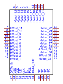
Schematic symbol for HV5622
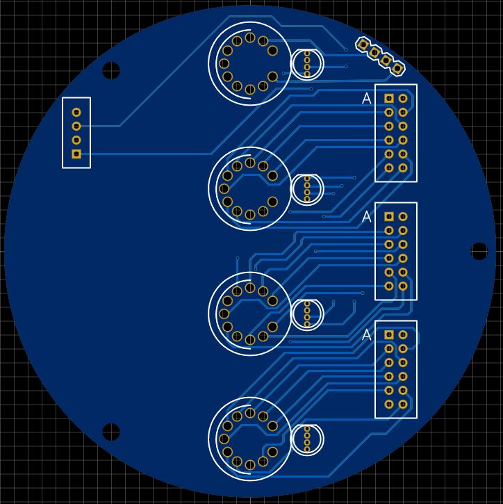
A tube board for four IN-8’s
HV5622 driver
As well as replacing three chips and the opto couplers in the original design, the HV5622 provided the additional benefit of having 32 outputs – 12 more than I needed for the two digit clock design.
Great I thought, lets make a 3 digit clock. I thought about this for quite some time and concluded that the appeal for displaying the time on three digits was somewhere between limited and zero.
What we really needed was 4 digits so at least time could be properly displayed.
Accordingly the last two outputs have been deployed to display either ‘1’ or ‘2’ on the fourth tube, excellent. A 4 digit direct drive clock using only 32 driver outputs. OK, its not a real 4 digit clock because the 4th digit can only ever display a ‘1’ or a ‘2’ – some may say that’s a waste of a tube though in reality, given that it can be used for 12hr clock, 24hr clock, and display the pressure in millbars, what’s the issue?
I’ll not claiming that it’s a 4 digit clock but actually a 3.1 digit clock, lets call is Dobly!
Still more to do…..
This design is very much at the ‘.0’ stage and there are still several things to be sorted out, component footprints verified, some things to be moved, better power connection to be added, oh, and testing to see if I can actually make the thing work but it’s all crawling along nicely!
Boards for Dobly 3.1.0 are on their way, they should be fine and certainly capable of doing the job though I am constantly refining things. I find that I often come up with (what i think are) great ideas, most usually immediately after ordering a set of boards!
One interesting challenge was in allocating the various outputs of the Wemos to various tasks whilst dealing with their limitations:
Not all pins support PWM, some pins affect the way that the Wemos boots (or doesn’t!) and some pins do not have internal pullup resistors (needed for the optional PIR connection).
This had been fine until I decided to implement SPI data transfers from the Wemos to the HV5622 rather than simply bit-bashing the outputs. This required some pins to be swapped about and it took me a while to settle on a combination that actually met all the criteria but it’s done now.
The benefit of using SPI transfers is that it’s all ‘done in hardware’ and is not reliant on your porgam code to perform the transfer – this detracts from one’s code’s ability to cause Watchdog Timer errors because it is hogging the processing wheras the Wemos has far more important things it would rather be doing like running the WiFi connection and SPI transfers!
Once the four tube boards turn up I can get the 4 tube code tested. I’d also like to use the under tube lighting a little more to indicate different functions, especially when showing data on four tubes like DD, MM where the DD and MM are underlight by different colours – perhaps?!?
Whilst I settled on IN-8’s for a four tube design, there may be interest in using other tubes. To that end I have laid out an adapter board which will accept four ‘standard’ tube cells – like those used on the PV Electronics QTC Clocks (which is how I got in to this whole thing in the first place). It does add about 12mm to the height of the clock but will mean that any tube could be used as long as there are tube cells available for the tube in question. Many are available directly from PV Electronics, I have created many of these for other tube types.
Curently the following tube boards are available:
4 x PV Tube Cells
4 x IN-8
2 x IN-18
2 x Z566M and compatible tubes
2 x ZIN-18
I have created individual tube-cell boards for the following tubes:
• ZM1000
• ZIN-18
• IN-18
• Dalibor Farnys tubes
• GNP7A
• GNP-17A
• XN-12
• XN-3
• CD-66(DL)
• Z566M/ZM1040
• ZM1177
• ZM1175
All these tube cell PCB’s have been designed so that the tube fits without any twisting or bending of leads which is helpful if you are using tubes recovered from old equipment which may have short and/or fragile leads.
I have recently trialled yet another microwave sensor module for motion detection with complete success and I’ll be building a couple of clocks which feature these.
Having the clock on only when you are in the room should extend tube life many times.
The Round PCB lends itself to a round casing and I have used several of the glass dome style bell-jar / closhes which are readily available on the bay.
*UPDATE
I just assembled three clocks on updated boards and it all went well. I discovered a design faux-pas on the tube boards, the ‘footprint’ I had used for the APA-106 LED’s was wrong and had the power connections reversed. All the LED’s lit up ever so briefly on power on then never again! Som eleg swapping confirmed the situation and the LED’s can be mounted with the centre pair of legs crossed using suitable insulation – board designs updated so if I ever order more – things will be easier!
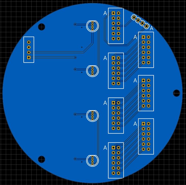
A tube board that will allow the mounting of 4 tube cells from PV Electronics which means that many small tube types are supported.
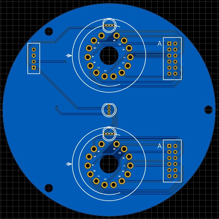
A Tube board for two IN-18’s